- 您现在的位置:买卖IC网 > Sheet目录63 > OPB917IZ (TT Electronics/Optek Technology)SWITCH SLOTTED OPTICAL WIRE LDS
OPTEK Technology Inc. 1645 Wallace Drive, Carrollton, Texas 75006
Phone: (972) 323-2200 or (800) 341-4747 FAX: (972) 323-2396 sensors@optekinc.com www.optekinc.com
Issue B 04/2013
Page 2 of 4
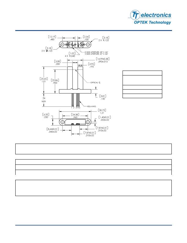
Photologic?Slotted Optical Switch
OPB917 Series
OPTEK reserves the right to make changes at any time in order to improve design and to supply the best product possible.
DIMENSIONS ARE IN:
INCHES
[ MILLIMETERS]
Absolute Maximum Ratings (T
A
=25癈 unless otherwise noted)
Storage & Operating Temperature Range
-40癈 to +80癈
Lead Soldering Temperature [1/16 inch (1.6mm) from the case for 5 sec. with soldering iron]
(1)
260癈
Input Infrared LED
Supply Voltage, V
CC
(not to exceed 3 seconds)
18 V
Input Diode Power Dissipation
(2)
100 mW
Forward DC Current
50 mA
Output Photologic?
Voltage at Output Lead (Open Collector Output)
35 V
Diode Reverse DC Voltage
2 V
Output Photologic?Power Dissipation
(3)
90 mW
Notes:
(1) RMA flux is recommended. Duration can be extended to 10 seconds maximum when flow soldering.
(2) Derate linearly 1.33 mW/癈 above 25?
(3) Derate linearly 2.50 mW/癈 above 25?
(4) Normal application would be with light source blocked, simulated by I
F
= 0 mA.
(5) All parameters tested using pulse technique.
Color
Description
Red
Anode
Black
Cathode
Green
Emitter
Blue
Output
White
V
CC
发布紧急采购,3分钟左右您将得到回复。
相关PDF资料
OPB940W51Z
SWITCH SLOTTED OPTICAL WIDE GAP
OPB950
ENCODER DUAL CHANNEL SNAP MOUNT
OPB993T11Z
SWITCH SLOTTD OPTICAL PHOTOLOGIC
OPS693
SNSR OPTO TRANS TH MOD PHOTOTRAN
QVA21114
SENS OPTO SLOT 3.18MM TRANS THRU
QVE00039
SENS OPTO SLOT 2.41MM TRANS C-MT
QVE11233
SENS OPTO SLOT 3.81MM TRANS THRU
RPI-0125
SENSOR OPTO SLOT 1.2MM TRANS SMD
相关代理商/技术参数
OPB920AZ
功能描述:光学开关(透射型,光电IC输出) Slotted Opt Switch RoHS:否 制造商:Optek 输出设备:Totem Pole, Buffer 槽宽:3.18 mm 光圈宽度:1.27 mm 正向电流:40 mA 最大工作温度:+ 70 C 最小工作温度:- 40 C 封装:
OPB920BZ
功能描述:光学开关(透射型,光电IC输出) Slotted Opt Switch RoHS:否 制造商:Optek 输出设备:Totem Pole, Buffer 槽宽:3.18 mm 光圈宽度:1.27 mm 正向电流:40 mA 最大工作温度:+ 70 C 最小工作温度:- 40 C 封装:
OPB920CZ
功能描述:光学开关(透射型,光电IC输出) Slotted Opt Switch RoHS:否 制造商:Optek 输出设备:Totem Pole, Buffer 槽宽:3.18 mm 光圈宽度:1.27 mm 正向电流:40 mA 最大工作温度:+ 70 C 最小工作温度:- 40 C 封装:
OPB920DZ
功能描述:光学开关(透射型,光电IC输出) Slotted Opt Switch RoHS:否 制造商:Optek 输出设备:Totem Pole, Buffer 槽宽:3.18 mm 光圈宽度:1.27 mm 正向电流:40 mA 最大工作温度:+ 70 C 最小工作温度:- 40 C 封装:
OPB930
制造商:OPTEK 制造商全称:OPTEK 功能描述:Photologic㈢ Slotted Optical Switch
OPB930L
制造商:OPTEK 制造商全称:OPTEK 功能描述:Photologic Slotted Optical Switches
OPB930L51
功能描述:光学开关(透射型,光电IC输出) Slotted Opt Switch RoHS:否 制造商:Optek 输出设备:Totem Pole, Buffer 槽宽:3.18 mm 光圈宽度:1.27 mm 正向电流:40 mA 最大工作温度:+ 70 C 最小工作温度:- 40 C 封装:
OPB930L55
功能描述:光学开关(透射型,光电IC输出) Slotted Opt Switch RoHS:否 制造商:Optek 输出设备:Totem Pole, Buffer 槽宽:3.18 mm 光圈宽度:1.27 mm 正向电流:40 mA 最大工作温度:+ 70 C 最小工作温度:- 40 C 封装: